Code your own low-pass or shelving filter plugins.
You probably have seen some form of a parametric equalizer in your digital audio workstation. You may be familiar with low-pass or notch filters. How to design them? How to implement them in code as plugins?
In this article, I will outline 4 steps necessary to create such software. By the end of this article, you will know exactly what to do when you want to implement a parametric filter, even if it’s just for a university or hobby project.
Basic Definitions
An equalizer (EQ) is a software program or a device that allows you to adjust the volume of specific frequency ranges. Two main classes of equalizers are parametric equalizers and graphic equalizers [VälimäkiReiss16].
A parametric equalizer is an equalizer that gives you the greatest amount of control: you can specify exactly which frequency ranges you want to affect and how much. As such, it is the most powerful and flexible equalizer of all [VälimäkiReiss16]. A parametric EQ consists of different types of parametric filters, which are aligned in a series (a cascade).
 Figure 1. Parametric EQ plugin consists of cascaded parametric filters.
An audio plugin is a piece of software that runs inside a digital audio workstation (DAW) to modify a certain track containing audio recordings. Sample plugin formats are: VST, AAX, AU.
 Figure 2. Graphical user interface of ReaEQ parametric equalizer plugin.
In this article, we will discuss how to design and implement a parametric EQ audio effect plugin.
Plugin Requirements
Let’s ask ourselves the question: what are the design requirements of our filter plugin?
If you come from the digital signal processing field, you may be familiar with finite impulse response (FIR) filters or infinite impulse response (IIR) filters. You may know that there are dozens of methods for creating these filters. However, in the context of audio plugins, our filters need to have specific properties:
1. Meaningful Controls
For example, a low-pass filter may have a cutoff frequency parameter and a resonance parameter, both of which are well defined and understandable even to people untrained in digital signal processing.
 Figure 3. Physically interpretable controls of a low-pass filter.
As opposed to that, if I gave you control over filter coefficients, like
2. Computational Efficiency
In the context of filters, it usually means that we will favor IIR filters because they have low processing delay [VälimäkiReiss16]. There is an additional reason for this: the controls-to-coefficients mapping must be fast as well. If we were to design the transfer function and derive the impulse response of an FIR filter every time we turn a knob on our plugin’s interface, we wouldn’t be able to operate in real time.
3. Stability For Any Meaningful Parameter Setup
In other words, if we turn a knob, we must be sure, that the output of the plugin won’t start increasing into infinity. The stability is acquired through using so-called analog prototypes, which I will cover shortly.
4 Steps To Design A Parametric Filter Plugin
Now, when we know, what is important for a musically useful plug-in filter we can cover the 4 steps necessary to design it:
- Decide on the filter type you want to implement.
- Design an analog prototype.
- Digitize the analog prototype using the bilinear transform.
- Implement the digital filter in code.
There’s one additional step that I encourage you to do now that will allow you to excel at audio programming in general: subscribing to the WolfSound email list. If you haven’t done that already, please, do it now. Thank you: each and every subscriber makes me want to do more articles and videos so that you can enjoy the beauty of audio programming.
Let’s now elaborate on every of the 4 steps.
Step 1: Decide On The Filter Type
In digital signal processing, there are lots of filter types but in parametric EQs there are only a few. I will shortly explain the most important ones now. With each filter type you will see its amplitude response. Below, I listed the control parameters of each filter.
In Short
Filter Controls
| Filter Type | Controllable Parameters |
|---|---|
| Low-Pass, High-Pass |
|
| Band-Pass, Notch |
|
| Shelving |
|
| Peak |
|
Note: the naming conventions used in the context of filters vary wildly. I tried to follow the ones used in [VälimäkiReis16] and [Zölzer11] but even they not always agree. If something’s unclear, please, ask about it in the comments underneath the article.
Low-Pass Filter
A low-pass filter attenuates all frequencies higher than the cutoff frequency.
 Figure 4. Low-pass filter amplitude response.
The cutoff frequency is the frequency at which the filter attenuation is -3 dB relative to the unfiltered signal. Another parameter is the resonance. Resonance let’s you create a peak around the cutoff frequency in the amplitude response of the filter. The resonance was probably the main factor behind the success of the Moog synthesizer filter section.
 Figure 5. Keith Emerson playing the Moog synthesizer.
Additionally, we can control the roll-of, i.e., the slope of the filter so how fast is the amplitude response decaying above the cutoff frequency.
In itself, the low-pass filter is a powerful musical tool.
High-Pass Filter
A high-pass filter works exactly the same as the low-pass filter, except that it attenuates frequencies below the cutoff frequency. All the parameters are the same as for the low-pass filter.
 Figure 6. High-pass filter amplitude response.
High-pass filter is usually used to remove undesired frequencies below 100 Hz.
Band-Pass Filter
A band-pass filter passes through frequencies only in a certain range. It cannot additionally boost or attenuate them. The only two parameters it lets us control is the center frequency of the band and the bandwidth or, alternatively,
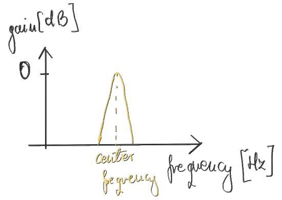 Figure 7. Band-pass filter amplitude response.
Notch Filter
A notch filter also called a band-stop or band-reject filter does the opposite than the band-pass filter: it eliminates a certain frequency range from the signal. Again, we can control it through center frequency and bandwidth (or
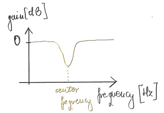 Figure 8. Notch filter amplitude response.
Shelving Filter
Milder versions of the low-pass and high-pass filters are high-shelving and low-shelving filters respectively.
A high-shelving filter lets us boost or attenuate frequencies above the crossover frequency. The crossover frequency specifies the frequency at which the filter’s gain reaches half of the shelf gain
 Figure 9. High-shelving filter amplitude response.
A low-shelving filter, as you might guess at this point, lets us manipulate the shelf below the crossover frequency. It has exactly the same parameters as the high-shelving filter.
 Figure 10. Low-shelving filter amplitude response.
Peak Filter
The final filter that is musically useful is the peak filter also called a peaking or band filter. A peak filter lets us boost or attenuate a frequency range. We can control the center frequency and the relative bandwidth (
 Figure 11. Peak filter amplitude response.
Now that you know the types of the filters, you can decide on which of them you want to implement. Even if you want to implement them all, start with a single, specific filter. You have it? Then it’s time for step 2.
Step 2: Design an Analog Prototype.
An analog prototype ensures that we have meaningful controls-to-coefficients mapping and we obtain a computationally efficient and stable IIR filter. To design an analog prototype to obtain a desired filter type, we need to turn to analog filter design theory.
Without going into much detail, there are 4 main classes of analog filter design [Smith07,Moore90]: Butterworth, Bessel, Chebyshev, and Elliptic Functions. Each of them is optimal in some sense. Using these, we can construct any of the above-specified filters in the analog domain. The output of this design is an analog transfer function in the Laplace domain (
For example, the first-order analog Butterworth low-pass has the following transfer function
where
Step 3: Digitize the Analog Prototype
The third step to implement a filter plugin is the digitization of the analog prototype. Again, there are many ways to do this but in practice the one most useful for musical purposes is the bilinear transform, also called Tustin’s method [Smith07,VälimäkiReiss16,Zölzer08,Zölzer11].
The bilinear transform maps the analog frequencies from the
![]() Figure 12. Bilinear transform formulas.
Figure 12. Bilinear transform formulas.
For audio purposes,
For example, the first-order low-pass filter from Eq. 1 after digitization becomes
Can you now go back to the analog transfer function via the substitution for
Shortcut To Steps 2 and 3
There is a trick that allows you to shortcut steps 2 and 3. The so-called Audio EQ Cookbook, compiled by Robert Bristow-Johnson (thus, sometimes called “RBJ Cookbook”), already lists most of the musically useful filters in their digital forms so you don’t have to derive them all over again. Nevertheless, I still believe it is beneficial to understand the process that stands behind these formulas in order to use them to their full capacity and be able to extend them if necessary.
Step 4: Implement the Digital Filter
The last step in the process is to take that digital filter and implement it in the technology of your choice. Sample technologies may be
- Python,
- Rust,
- Matlab,
- CSound,
- Pure Data,
- Android,
- iOS,
- JavaScript
- Arduino,
- Raspberry Pi, or…
- JUCE.
The last option may seem the most obvious choice for audio plugin developers, that is why, I will be showing you how to implement each and every of the mentioned filters in the JUCE C++ framework over the course of the following articles and videos. So stay tuned!
Applications of Parametric Filters
So where can these parametric filters be applied? One obvious answer is your digital audio workstation. In this software, you can use a parametric EQ plugin to manipulate the frequency content of your audio tracks [VälimäkiReiss16]. Thanks to these plugins, you can remove unwanted tones or wide-band noise and add coloration to the timbre. However, that’s not the only use.
Efficient filters are especially important in game audio, virtual reality, or, in a broader sense, the field of sound design. Any virtual environment must be able to dynamically control user’s environment and tune the system so that the changes in player movements are reflected in the changes in sound. One example could be filtering applied when a player finds themselves behind a curtain; the sounds coming from behind should sound muffled what can be achieved with a low-pass or a high-shelving filter. A similar effect can be put on audio when the player finds themselves under water.
Summary
In summary, in this article I showed you 4 steps to create a filter plugin: from an idea to the implementation. I have also showed you a shortcut in the form of Audio EQ Cookbook.
Over the next couple of articles and videos, I will discuss in detail every step so that you can understand fully the process behind parametric EQ design and implementation. Then I will show you sample implementations of the parametric filters in the JUCE C++ framework in the form of do-it-yourself plugin tutorials. So there is a lot ahead of us!
If you want to be notified about weekly WolfSound content in a condensed form, subscribe to my email list.. Thank you!
Bibliography
[Moore90] F. Richard Moore, Elements of Computer Music, Prentice Hall 1990.
[Smith07] Julius O. Smith, Introduction to Digital Filters with Audio Applications, http://ccrma.stanford.edu/~jos/filters/, online book, 2007 edition, accessed November 26, 2021.
[VälimäkiReiss16] Vesa Välimäki, Joshua D. Reiss, All About Audio Equalization: Solutions and Frontiers [PDF], Applied Sciences, Vol. 6, Issue 5, May 6, 2016.
Robert Bristow-Johnson, Audio EQ Cookbook.
Links above may be affiliate links. That means that I may earn a commission if you decide to make a purchase. This does not incur any cost for you. Thank you.
Comments powered by Talkyard.